

This exercise is a bit different. Instead of merely observing packets, we are going to be directly involved in their journey by simulating a network using GNS3. Let us start the fun!
Item 1: Planning the network
For this exercise, we are making a network with a /20 subnet mask. This allows for some flexibility (as the prompt tells us that we are going to be using this for a university with many campuses), while at the same time being cost-effective as globally routable IP ranges are becoming more expensive as IPv4 addresses are exhausted.
With that, I selected an arbitrary subnet address, which is 21.67.80.0/20. After that, we are going to partition the network according to the allocation required by the exercise.

As can be seen in the above figure, we are going to divide the subnet into four /22 subnets. Following the above figure a little bit too literally, this means:
| Subnet | Bitmask | Start Address | End Address |
|---|---|---|---|
| Reserved | 22 | 21.67.80.0 | 21.67.83.255 |
| Campus A | 22 | 21.67.84.0 | 21.67.87.255 |
| Campus B | 22 | 21.67.88.0 | 21.67.91.255 |
| Reserved | 22 | 21.67.92.0 | 21.67.95.255 |
Then, we are going to divide each /22 according to the diagram. Using Campus A as an example, this means:
| Subnet | Bitmask | Start Address | End Address |
|---|---|---|---|
| Blue | 24 | 21.67.84.0 | 21.67.84.255 |
| Green | 24 | 21.67.85.0 | 21.67.84.255 |
| Reserved | 24 | 21.67.86.0 | 21.67.86.255 |
| Servers | 25 | 21.67.87.0 | 21.67.87.127 |
| Point-to-point (32 x /30) | 25 | 21.67.87.128 | 21.67.87.255 |
A sample point-to-point subnet is also detailed below:
| Subnet | Bitmask | Start Address | End Address |
|---|---|---|---|
| Point-to-point (sample) | 30 | 21.67.88.128 | 21.67.88.135 |
Just for reference, here's campus B:
| Subnet | Bitmask | Start Address | End Address |
|---|---|---|---|
| Blue | 24 | 21.67.88.0 | 21.67.88.255 |
| Green | 24 | 21.67.89.0 | 21.67.89.255 |
| Reserved | 24 | 21.67.90.0 | 21.67.90.255 |
| Servers | 25 | 21.67.91.0 | 21.67.91.127 |
| Point-to-point (32 x /30) | 25 | 21.67.91.128 | 21.67.91.255 |
Item 2: Setting up the network
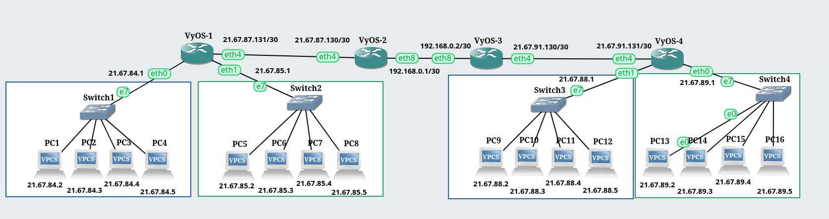
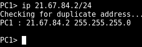
The network is set up as shown. For the particular PCs, I reserved the 21.67.xx.1 addresses for the routers and counted up from there to assign addresses to the PCs. For example, PC4 is 21.67.84.5.
Subnet testers
The routers are not configured yet, but we can test the subnets already. Let's try it!
a. From a PC in the Blue subnet, is it possible to ping another PC within
the same subnet? Why or why not?
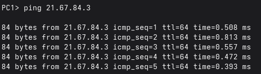
It is definitely possible to ping another PC within the same subnet as it makes a direct connection. This happens using ARP, which is outside of the scope of this exercise.
b. From a PC in the Blue subnet, is it possible to ping R1’s directly
connected interface? Why or why not?
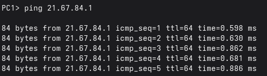
Yes, a PC in the Blue subnet can ping R1 directly since this interface is in the same subnet.
c. From a PC in the Blue subnet, is it possible to ping a PC in the Green
subnet? Why or why not?
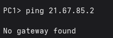
To test this, I pinged PC5 (in the Green subnet) from PC1 (in the Blue subnet). It did not succeed due to a No gateway found error. This means that PCs in each subnet do not know where to route the packets they intend to be sent to another subnet. It can communicate with the router at 21.67.84.1, however it is not configured as a router so it "doesn't know" that the devices at that IP address is a router.
Adding routes
Configure static routes in R1 such that you can ping across subnets, but only within
one campus for now.

a. From a PC in the Blue subnet, is it possible to ping a PC in the Green
subnet? Why or why not?
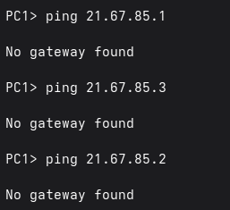
I have set static routes in R1 to route traffic to the Green subnet. But since the PCs do not know what router to use, pinging the Green subnet still returns a No gateway found error.
b. Configure all the hosts (PCs) in the campus you are working on such
that their default gateways are the R1 interfaces directly connected to
the same subnet as the host. Is it now possible to ping a PC in the
Green subnet from a host in the Blue subnet, and vice versa? What
effect, if any, did the presence of a configured default gateway make?
Explain your answer in detail.
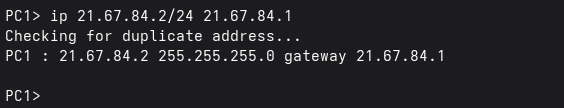
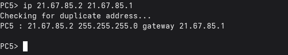

I then configured the gateways of the Blue and Green subnets, the gateways being 21.67.84.1 and 21.67.85.1 respectively. With this, the subnets are now able to ping each other.
Going inter-campus
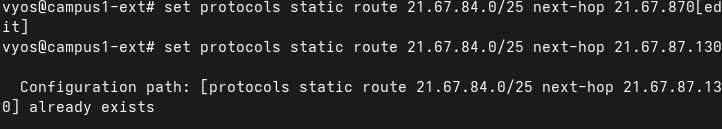
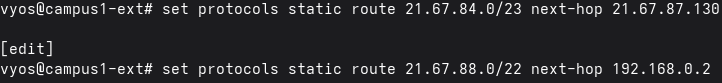
4. Configure static routes in R2 such that (1) it has a single static route to a /23 prefix which summarizes both the Blue and Green routes, and (2) it also has a single static route to a /22 prefix representing the opposite campus. Make sure you also perform the same configuration steps in the other campus.
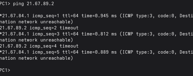
a. From a PC in one campus, is it possible to ping any PC in the other
campus? Why or why not?
No, since R1 has no configured route for the packets meant for the other campus. This means packets from a PC from one campus only get discarded and never reach their intended destinations. The router at R1 even gives us a clue on what's going on!
b. Configure a default route in R1 that points to R2’s directly reachable
network interface. Can you now ping any PC within the other campus?
What effect, if any, did the presence of a configured default gateway
make? Explain your answer in detail.


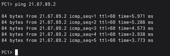
Adding a default route in R1 fixed the problem I encountered previously. The default route ensures that anything that is not meant for the same subnet and is not covered by R1's interfaces will be forwarded to R2. With this change, both campuses can now reach each other.
Conclusion
This exercise was a bit tedious, but it showed me how a network is built from the ground up, and it taught me not to take the dozens or hundreds of protocols across all the layers for granted. With a network as big as the Internet, I do not think that it will be manageable with the manual configuration I did on this exercise.